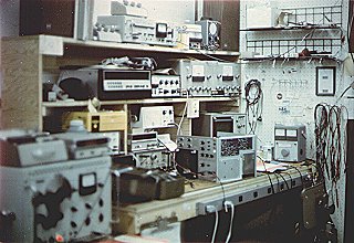
 I took this picture in 1974 and didn't pay too much attention to focus and lighting.
Anyway, my test equipment was all Heath products except for three instruments. In the lower left corner is a Radiometer RF generator. It's frequency range covered nearly every product Heath manufactured and would produce CW, AM, and mono FM signals. It was capable of both internal and external modulation. At turn-on, the frequency would drift, but would be rock-steady after an hour of warmup. Its output (both frequency and signal level) was extremely accurate, making it an excellent tool for testing and aligning Heath RF equipment.
On the top shelf (slightly left of center) is another Radiometer product, an FM stereo generator. It was mostly required for adjusting the "older" (with reference to the middle '70s) Heath FM stereo receivers, which had a half-dozen coils and potentiometers that needed tuning. The newer Heath products used a phase-locked loop that would bring maximum performance by adjusting one potentiometer while the radio was tuned to any FM station that was broadcasting in stereo.
The remaining non-Heath instrument is located on the bench next to the wall at the right near all of those cables. This is a Variac voltage-variable AC power supply and has saved me a lot of time troubleshooting kits with short circuit problems. You plug the kit into it, adjust the knob so the line voltage rises from zero volts to 120 VAC. If the current meter needle slams over to the right at about 5 VAC, you back it down and start testing and analyzing why it's doing that.
Of all the Heath test instruments, my two all-time favorites are the IM-28 VTVM and the IO-105 oscilloscope.
The IM-28 is located near the center of the picture and is mounted beneath the middle shelf. The circuitry is the same as the IM-18 VTVM, which hadn't changed much since the early '50s. It was rugged and reliable for most work. I'd used digital multimeters for critical measurements, but an analog meter worked best when tuning a product for peak performance.
The IO-105 dual-trace oscilloscope is located on the surface of the bench next to the wall and just to the left of the Variac. There's an IO-104 scope (that I was servicing at the time) laying on its side and partially obscuring it.
During the '70s (and maybe even today), an oscilloscope was one of the best tools a technician could have. If you used a signal generator and sent a signal to the equipment you were testing and it didn't come out as expected (slow rise-time, poor frequency response, etc.), using the scope would help you to quickly locate the circuitry the defective component was in. I liked the IO-105 because it was dual-trace, stable, accurate, and reliable.
 On the top of my workbench--on the right and left (barely visible)--are a set of
speakers (either AS-102s or AS-103s) that I used to test the sound quality of audio
equipment I'd repaired. When the AA-1640 Power Amplifier came out, I added a large
set of resistive loads to a heat sink under my bench. (The AA-1640 was spec'd at 200 watts
continuous power into 8 ohms per channel, but could easily do 300 watts before audible distortion
crept in.)
Two small boxes on the top shelf--one on top of the Radiometer, the other just to the left--are capacitor and resistor substitution boxes, respectively. They came in handy when trying to figure out why a circuit wasn't doing what it was supposed to do.
To the right of the Radiometer FM stereo generaor is a 0-15 VDC power supply that I used to test some of the smaller Heath products. If I remember right, that scope next to it was used to test the chroma circuits of television sets. I didn't use it that often since we had a full-time TV tech.
On the second shelf and on the left is an AJ-1510 FM digital tuner. I used it as a test fixture to service customer's circuit boards. In my five years at the Omaha store, only two AJ-1510s came in for service. After the product went off the market, I purchased the fixture and added it to my home stereo system.
To the right of the AJ-1510 is an IG-18 audio sine/square-wave generator. I used it a lot to test audio and (sometimes) digital circuits. To its right are two other audio test instruments: An IM-48 total harmonic distortion meter, and an IM-38 intermodulation distortion meter. I used these when performing final checks on sound systems to make sure they met specifications.
On top of the Radiometer (lower left corner) is an IB-1103 frequency counter. It's a must-have instrument if you're working on equipment requiring accurate frequency adjustments. To the right of it--beneath the IM-28--is a Heath digital voltmeter. I can't remember the model number, but it came in handy when accurate measurements were needed.
Beneath the DVM is a resistive load box that allowed testing stereo amplfier outputs
under 4-, 8-, and 16-ohm loads. It could test all the Heath audio amplfiers except the
AA-1640 (see above).
